Revolutionizing Circuit Design with Hardware Description Languages
For many budding engineers and electronics enthusiasts, the traditional approach to circuit design often starts with schematicsa graphical representation of the components and their interconnections. However, as electronic designs become increasingly intricate, managing complex circuits with conventional schematics can become burdensome and tedious. In light of these challenges, modern designers, particularly those working on digital circuits, are increasingly turning to hardware description languages (HDLs) as a more efficient alternative.
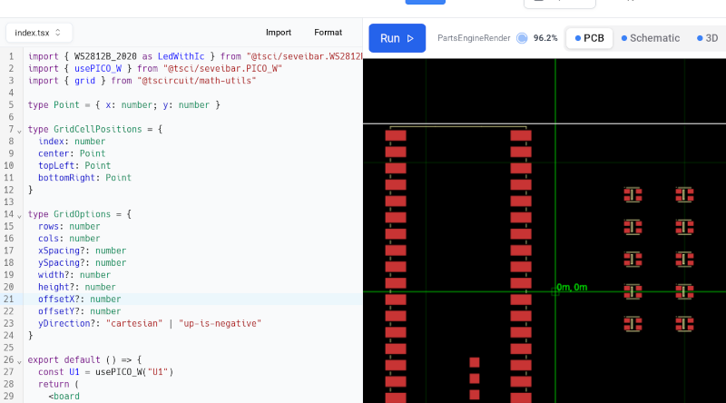
Among the various tools available for PCB (Printed Circuit Board) layout, one noteworthy option is tscircuit. This innovative platform offers a user-friendly approach to circuit design, enabling users to create layouts for various applications, including LED matrices. For those interested in exploring this tool, there is a detailed walk-through available that guides users through the design process. Whats more, you can even try it out online, allowing for immediate hands-on experience without the need for installation.
For visual learners, tscircuit also provides a helpful introductory video that outlines the key features and functionalities of the tool. In a recent example project showcased on the platform, users can import a Pico microcontroller along with smart LEDs. While these components are visually represented, the real power lies in the ability to manage connections through code, rather than traditional graphical methods. For instance, a simple line of code might look like this: <trace from={".LED1 .GND"} to="net.GND" />. This syntax may resemble HTML, which reflects the shift towards a more coding-oriented approach in electronic design.
Once users create their schematic, they can seamlessly transition to laying out the PCB. This process involves using footprints that correspond to the components used in the schematic. The platform enhances user interaction by allowing users to load the design directly in their web browser, where they can make modifications in real-time. At the top right of the interface, various buttons provide access to different views, including the schematic, the board layout, a 3D render of the board, a bill of materials (BOM), assembly drawings, and other output formats.
As for whether this approach will gain traction among designers, it's still an open question. Historically, there was significant resistance to adopting HDLs for Field Programmable Gate Arrays (FPGAs), but as these devices have expanded in complexity, many designers now prefer HDLs over endless pages of schematics. This leads to a pivotal inquiry: Will you choose to utilize this innovative tool in your designs? We invite you to share your thoughts in the comments section below.
Its important to note that the concept of using HDLs for circuit design isn't entirely new. The real challenge lies in determining which HDLs will thrive and which may fade away in the competitive landscape of electronic design.